Description
This product is one of the three wire-in universal ECUs we have for our line of Modular ECUs.
Our main objective in creating the Adaptronic Modular ECU line is to further work towards Adaptronic’s mission which is to give people control. In doing this, we came up with a system which would give people greater flexibility and at the same time, overcome the limitations of our older product line – the Select ECUs.
The base M2000 is an ECU that can be expanded to have more analogue 0-5v inputs, real-time / frequency inputs, auxillary outputs, or to be able to control a single electronic throttle. Injector and Ignition outputs are fixed at eight channels each. There is only one expansion slot in the M2000, so the user will have to choose which type of expansion (i.e. upgrade module) he would need. This may be done upon purchase or even at a later time. If this is a limitation for the application then we recommend using an M6000 ECU instead. Existing M2000 users can easily upgrade to an M6000 ECU if need be, as the main ECU pinouts are identical between the two ECUs.
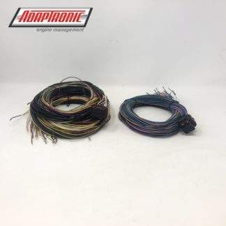
Connectors and looms are sold separately.
WHAT’S IN THE BOX?
- Engine control unit (connectors or loom sold separately)
- USB (tuning) cable
- 1GB USB Stick
- Adaptronic Sticker
GENERAL FEATURES
– Modular system, so that people can buy hardware upgrades later as their needs develop (eg additional inputs, outputs, or specific functions, eg drive by wire or built-in lambda)
– Offer a waterproof option, using Superseal connectors
-Wireless communication
-Fast USB communication, requiring no drivers
-Headphone port for listening to the knock sensor while tuning
-4 x serial ports
-1 x CAN port
-Power over USB to do loading of maps, firmware etc without having to provide it with 12V power
– 32MB of onboard logging to flash
-Exception logging, able to detect faults and log a bunch of things that happen around the same time to help with ECU setup and tech support
-Bigger maps, more of them, and more dedicated maps.
-Tested to MIL-STD-202G, a military vibration standard, which varies the frequency and peaks at 7.5g of oscillating acceleration
FEATURES / SPECIFICATIONS
| Variable |
Number |
Details |
| Analogue 0-5V inputs |
11 |
Each is 0 – 5.5V, 55k input impedance
- 2 x TPS / pedal position
- 6 x pressure – Oil, Fuel, Internal intake MAP, internal exhaust MAP, external intake MAP, external exhaust MAP
- 3 x spare for servo feedback / external inputs
|
| Analogue oxygen sensor inputs |
2 |
Each can be either:
- 0 – 5.5V, 55k input impedance
- 0- 3.3V, 1M input impedance
|
| Temperature inputs |
4 |
Each is 0 – 5.5V, 55k input impedance to ground
Each can be:
- Non-biased, eg in piggyback mode. Calibration is in mV
- Biased, calibration is in Ohms. 3 internal pull-ups, 1k5, 2k2, 4k7, automatically selected by the ECU
Manifold air temperature, coolant temperature, oil temperature, fuel temperature |
| Crank trigger inputs |
3 |
- Selectable 2k2 pullup (on in digital mode, off in reluctor mode)
- Variable voltage trigger threshold from 0 to 65V – either arm input for reluctor or threshold for digital input
- AC coupled zero crossing trigger in reluctor mode
- Variable filtering 1 to 192 µs
- See built-in scope section
|
| Vehicle speed input |
1 |
- Selectable 2k2 pullup
- Variable voltage trigger threshold from 0 to 65V
- Variable filtering 1 to 192 µs
- See built-in scope section
|
| Sensor power and ground |
|
- 5V regulated output for sensors, max 100 mA, current limited (voltage is monitored by ECU)
- Sensor ground connected to ground inside ECU under firmware control to detect external ground loops in the wiring (voltage is monitored by ECU)
|
| Knock input |
1 |
- 50 k input impedance
- Sampled at 80 kHz (12-bit resolution, 3.3V peak to peak max voltage),
- Variable second order highpass and lowpass filters
- Selectable start and end of sampling windows (in crank angle)
|
| Wired Outputs |
2 |
- Dedicated outputs for tacho and EFI relay
- Tacho output has inductor to generate back-EMF spike for impulse tachometers.
- EFI relay output can be configured as fuel pump or EFI relay. Switches to ground, current limited to 600 mA
|
| Headphone output |
1 |
Mono output, can be selected as direct knock input or filtered knock input |
| Power sources |
3 |
ECU can be powered by 12V EFI input, ignition switch, or USB (USB for settings / firmware upgrades / log retrieval only; 12V must be applied to read inputs) |
| CAN channel |
1 |
- Up to 1 Mbps
- Internal 120 Ohm terminating resistor can be turned on and off with ECU setting on each channel
|
| USB connection |
1 |
- Standard USB mini AB connector.
- 12 Mbps max speed
- USB appears as mass storage device (USB stick); no drivers are necessary
- Software installer included on mass storage device
|
| Serial connections |
4 |
- All 4 use 4-pin Molex connectors
- 2 x serial in (ground, transmit, receive)
- 1 x serial out (ground, transmit, receive)
- 1 x controller out (ground, transmit, receive and 12V switched, current limited power) – eg for dash, hand controller
|
| Wireless connection |
1 |
- Access point
- 230kbps max speed
- Settings and live data only (no log retrieval due to speed)
|
| Inbuilt sensors |
|
- Microphone
- 3 axis accelerometer
- 3 axis rate gyro
|
| Inbuilt logging |
32 MB |
- Max 30 hrs @ 10 Hz, 13 channels
- Min 20 mins @ 100 Hz, 125 channels
|
| Exception (fault) detection |
16 MB |
Separate logging memory for storing logs during “exceptions” (sensor / trigger faults etc) |
| Built-in scope |
4 channels |
- Max sample rate 200 kHz (5µs sample period)
- 1000 samples per screen (min 5ms across the screen)
- Analogue trigger inputs sampled at 40 kHz
Channels include
- Analogue CAS inputs
- Peak detected CAS voltages
- CAS threshold voltages
- Filtered CAS inputs
- Analogue external inputs
- Raw and filtered knock waveforms
- Current engine angle
- Calibrated input values
- Intermediate calculation values
- Output calculated values
|
| Main loop execution speed |
|
Variable depending on tuning mode and corrections enabled, 400 Hz nominal |
| Number of injector outputs |
8 |
- Switching topology for low heating
- Peak and hold current waveforms
- Programmable peak and hold current
- Max current per channel 4A continuous
- Nominal current per channel 1A (can be controlled in software)
- Unused injector outputs can be configured as auxiliary outputs, PWM capable, but only switching to ground
- Output voltage and current monitored
|
| Number of ignition outputs |
8 |
- Appears as a 470 Ohm to supply when high, short to ground when low
- Current limited output
- Unused injector outputs can be configured as auxiliary outputs, PWM capable, but only switching to ground, and only low current
- Voltage and current monitored
|
| Number of aux outputs |
4 |
- Push-pull outputs (can drive high or low)
- High side current limited to 1.2A
- Low side current up to 4A continuous
- Can be PWM but not engine synchronous
- Voltage and current monitored
|
| Hardware upgrade |
1 |
- Small Modules ( analogue input, real – time input, drive – by – wire control and output module)
|
Only logged in customers who have purchased this product may leave a review.


Reviews
There are no reviews yet.